

Publications, Conferences, and Presentations
Throughout my career I have worked extensively in new technology development and R&D. It should be no surprise that much of what I have done is kept private as confidential information. Occasionally I have had an opportunity to present and publish; this page covers everything that I can share.
ASA-POMA Conference Paper
Microphone vibration sensitivity: what it is, why it is
important, and how to measure it
Charles B. King and Chris Monti
UPDATE: Because this POMA paper was the most popular download from POMA in recent history, we were invited to be on their "Across Acoustics Podcast," which published in June, 2024.
The MEMS microphone was introduced by Knowles in 2002. Since then, MEMS has taken over the world, with millions of microphones made daily. Many products have several MEMS microphones in a single device, including smart phones, earphones, smart speakers, laptops, and hearing aids.
In hearing aids, gain is applied to amplify sounds in the environment of the user. This allows the user to experience sounds that they otherwise would not be able to hear. Microphones are very good at measuring sound, but they also have some sensitivity to acceleration (vibration). The speakers in hearing aids can cause vibration and so vibration sensitivity can contribute to feedback. Feedback is an annoying squealing sound and is the same phenomenon that occurs at concerts when a singer gets their microphone too close to the speakers on the stage.
We were tasked with finding an improved test method for measuring vibration sensitivity, one that would produce a cleaner frequency response, be more accurate, and would be good enough to measure sensitivities in directions other than the most sensitive "z-axis" of the microphone. One of my team members, Charles King, proposed the idea of pairing two MEMS microphones. We immediately recognized that this solution was perfect for creating a quiet environment, with no extra acoustic stiffness, and a perfect zero acoustic pressure condition at the port.
The results were fantastic. We successfully created the most accurate and flexible test for microphone vibration sensitivity. Read the full paper for more information.

Above is a picture of a Comsol simulation of paired MEMS microphones showing the acoustic pressure developed with one G (9.81 m/s^2) of acceleration. The combined front volumes have zero acoustic pressure at a shared port surface. The back volumes have zero acoustic pressure at a plane that approximately intersects the center of gravity of their respective air volumes.
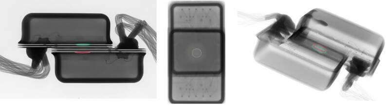
X-ray images of paired MEMS microphones prepared for vibration sensitivity testing.
ASA Conference Presentation
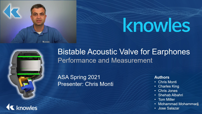
Performance and measurement of a bistable acoustic valve for earphones
This was a 2021 pre-recorded video talk for ASA (Acoustical Society of America). The video was removed from ASA's website after the talk and is not currently publicly available.
Abstract
Hearing devices often employ ear seals to optimize playback quality and reduce the leakage of low frequency signals. There are several downsides to having a fully blocked ear. One negative effect is the inability of the user to hear external sounds. Another downside of an ear seal is the introduction of occlusion effects, such as the amplification of the user's own voice. The ideal hearing device would have excellent sound reproduction but also avoid the negative effects of a sealed ear. One way to accomplish this goal is to have an earphone that can change states between being sealed and being open through a vent. An acoustic valve can be selectively opened and closed to change the state. Unlike active occlusion reduction and active pass through algorithms, a bistable valve will only consume power when transitioning between the open and closed states. In this talk, we present the important characteristics of an acoustic valve for battery-powered hearing devices. We explore the design and performance of one example acoustic valve. We discuss how to measure the acoustic performance of the valve and how the valve performs in real-world earphones. Practical considerations for in-ear valves are also examined.

ANSYS Level Up 3.0 Keynote Speaker
Maxwell and Mechanical Simulation of Balanced Armature Receivers
In 2022 I presented in a pre-recorded livestream about two case studies in which our team at Knowles utilized ANSYS simulation tools.
Link to Level Up (Note, content will eventually be removed)
See the ANSYS Blog Post below for a link to the second image.
Abstract
ANSYS Maxwell and ANSYS Mechanical transient simulations have been important tools at Knowles for reducing design cycles, cutting the cost of development, and improving time to market. We will present two recent case studies describing how the research and development team at Knowles used the unique capabilities of ANSYS to improve the design process of balanced armature receivers (BAs).
In the first case study Maxwell is used to model the demagnetization behaviors of the magnets we use in our BAs. In the second case study we combined in-house precision metrology with a variety of ANSYS simulation tools to develop a viscoplastic strain-rate-dependent material model for simulating transient mechanical shock events.


ANSYS Blog Post
Can You Hear Me Now? ANSYS Turns up the Volume on Hearing Device Designs
Link to the blog (including images)
Link to the Knowles version of the blog
In 2022 I worked with ANSYS on a blog post describing some of the ways our New Technology Development Team at Knowles uses ANSYS to innovate. ANSYS has clear strengths in single-domain simulation. I highlighted several examples, including the two case studies that were discussed in the Level Up talk.

SPIE 6665, New Developments in Optomechanics
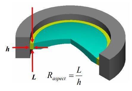
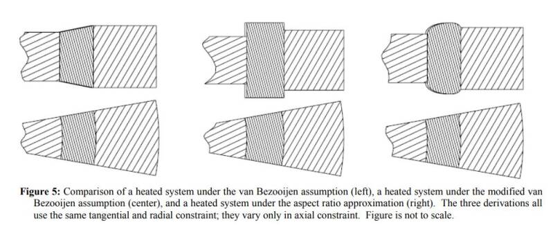
Athermal bonded mounts: Incorporating aspect ratio into a closed-form solution
Link to a full version hosted by the University of Arizona
Link to my presentation hosted by University of Arizona
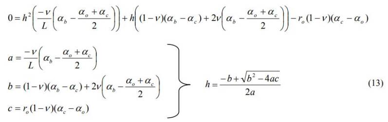
I am happy to see that this SPIE conference paper from early in my career is being cited and used by others for new design work. This 2007 paper identifies a hand calculation that can be used to find the near-ideal bondline thickness to minimize stress and deformation induced on a lens.
After publication I learned of a typo in the final equation. Please note the absence of the minus (-) sign in the last line definition of 'c'. It should be c=-ro(1-v)(ac-ao).
Abstract
Several approaches have been used to calculate a closed-form solution for the athermal bond thickness for mounting optical elements. All of the previously developed closed-form solutions use the assumption that the bondline is thin with respect to the width of the bond in the axial direction. While this assumption is mathematically convenient, it is not empirically or theoretically supported. To compensate for the inaccuracies of these closed-form solutions, recent research using test data and finite element analysis has centered on generating empirically determined correction factors that are applied to the closed-form solutions for a zero-stress bond. In this paper an alternative closed-form solution that incorporates the bond aspect ratio is presented. The values generated from this formula are compared to the empirical results of a finite element analysis (FEA) study. An example case is used to compare the results provided by the different methods for calculating the ideal bond thickness.
Create Your Own Website With Webador